Measured performance
Air Leakage Testing and Verification: What the Numbers Can Prove
A blower door measures airflow needed to maintain a test pressure under a defined setup. It can quantify change and support diagnostics, but it does not identify every leak, certify indoor air quality, or approve an assembly.
On this page
The short answer
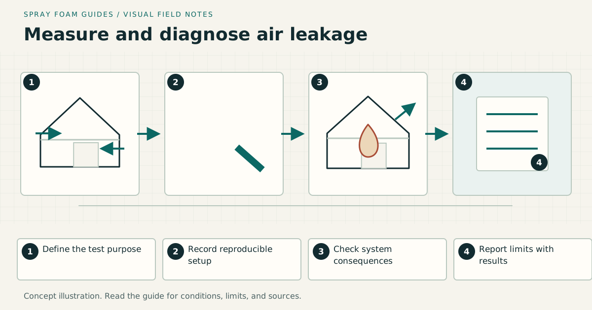
Write the test purpose, building configuration, equipment setup, weather, metrics, and diagnostic method before testing. Pair the number with location evidence, ventilation and combustion review, and a repair record.
This answer changes when…
- Test purpose, standard or program, building volume and enclosure area
- Doors, windows, dampers, drains, vents, fireplaces, and mechanical configuration
- Baseline, target, test pressure, units, uncertainty, and technician record
- Smoke, infrared, pressure-pan, zonal pressure, or other diagnostic limits
- Ventilation, combustion, radon, garage, and moisture consequences of tightening
Dotted terms have plain-language definitions. Browse the glossary ↗
Define the question before turning on the fan
A test may establish a baseline, find large bypasses, verify a program target, compare prework and postwork conditions, or diagnose a particular zone. Those purposes need different preparation and reporting. Write the purpose first so the operator knows what to include and what conclusion the result may support.
PNNL’s enclosure leakage guide describes a controlled pressure test of the building. The reported airflow belongs with the test pressure and setup. A bare number such as “1,200 CFM” is incomplete.
Record a reproducible configuration
Document which doors and windows were closed, which interior doors were open, how fireplace openings, exhausts, outdoor-air ducts, traps, dampers, and combustion equipment were treated, and whether attached spaces were inside the test boundary. Record building volume or enclosure area calculations when the reported metric uses them.
| Evidence | What it can support | What it cannot establish alone |
|---|---|---|
| Airflow at a stated pressure | Leakage magnitude under test setup | Exact leak locations or insulation quality |
| Normalized leakage metric | Comparison under the chosen method | Comfort, IAQ, or energy savings by itself |
| Smoke movement | Local flow direction during test | Natural-condition flow or safe chemical use |
| Infrared pattern | Surface-temperature differences under conditions | Moisture, missing insulation, or air leakage without corroboration |
| Zonal pressure | Connection strength between zones | Exact opening geometry or required repair |
| Pressure pan at register | Duct-zone connection under setup | Duct leakage quantity without the specified test |
Baseline and final tests must be comparable
Use the same recognized procedure, boundary, pressure, building dimensions, and configuration. Record equipment identification and calibration status, operator, date, weather, and unusual conditions. If the building changed size or a space moved inside the enclosure, explain how that affects normalized results.
A lower postwork value shows less measured leakage under the recorded setups. It does not prove that every targeted connection was sealed, that moisture will be safe, or that ventilation is adequate. Pair the result with photographs and a closeout inspection.
Diagnostics guide investigation, not blind sealing
Pressure-guided smoke or a theatrical fog method can reveal flow, but protect occupants, alarms, finishes, and sensitive equipment. Infrared work depends on temperature difference, surface properties, wind, solar history, and operator interpretation. Do not drill or fill a cavity solely from one colored image.
Use a leak inventory with location, connected zone, observed method, proposed repair, hazard screen, and outcome. A leak to an attached garage, crawl space, or attic deserves different treatment from leakage between two conditioned rooms.
Tightening changes the operating building
Before work, inventory fuel-burning appliances, exhaust devices, fireplaces, radon systems, attached garages, dryers, range hoods, and required outdoor air. Arrange the applicable combustion and ventilation assessments. After work, commission ventilation and repeat required safety tests under the responsible professional’s procedure.
A useful verification package
- State test purpose and governing procedure.
- Draw the tested boundary and calculate referenced dimensions.
- Record preparation, equipment, weather, and baseline result.
- Diagnose and photograph priority leakage paths.
- Screen each repair for water, fire, electrical, pest, and service conflicts.
- Inspect concealed work before closing assemblies.
- Repeat the test with comparable setup.
- Complete ventilation, combustion, and other required commissioning.
- Report results, uncertainty, changes, unresolved paths, and limitations.
Stop diagnostics around suspect hazardous material, unsafe electrical work, active combustion problems, contaminated spaces, or unstable assemblies. A strong report says what was measured, how, and what remains unknown. It never turns a pressure test into a blanket certification of the building.
Research & references
Sources used for this guide
- Enclosure Leakage TestDOE Building America Solution Center · government guidance · United States; blower-door measurement and diagnostic planning, with program protocol, combustion preparation, and acceptance limits verified for the project · accessed 2026-09-09
- Home Air Sealing ChecklistDOE Building America Solution Center · government guidance · United States · accessed 2026-09-05
- Consumer Guide to Air SealingU.S. Department of Energy · government guidance · United States; consumer guidance · accessed 2026-09-06
- Combustion Appliance Zone TestingDOE Building America Solution Center · government guidance · United States; qualified combustion-safety testing context, not a homeowner test procedure or universal pass threshold · accessed 2026-09-09
A citation supports a specific statement, not every possible assembly or local code interpretation.